Thursday, September 17, 2009

Appetizer Solar Robot

This miniature robot is derived from instructions provided on Chiu-Yuan Fang's website, from the BEAM community, and from Dave Hrynkiw. Some alterations are made based on the parts available.Appetizer solar robot.


Appetizer solar robot.
There are two major style changes:
  • Firstly, this robot drags the capacitor rather than pushing it.
  • Secondly, this robot carries its solar panel in front of it, like an appetizer tray.

Solar Robot Video

Video of Appetizer solar robot.
Click the above picture to see a video of Appetizer walking (or popping) in the early afternoon Colorado sun at 9,000 feet high. The video hasn't been sped up; this is the actual pace.

Solar Robot Schematic

Wiring diagram / schematic for a robot powered by a solar cell.
This is a schematic of a circuit that I altered slightly from Dave Hrynkiw's schematic. I posted the following questions on this page without thinking about who might read it. Turns out that Dave Hrynkiw himself kindly provided his thoughts and answers. Thanks Dave!
#1a Since they act like switches, transistors Q1N and Q2N appropriately don't have loads connected to their respective emitters. But then shouldn't they have current-limiting resistors (like 1 kilohm) connected to their bases? It would seem current is being wasted.
Dave responds: You know, that's a good point, and I don't think I've ever tried that. Just by looking at it, I think the issue may be suspending the 3906 collector too high above ground for it to remain on.
#1b It would also seem that there's a voltage drop problem from power (2.5 V) through Q1P (-0.6 V) through Q1N (-0.6 V) to ground (0 V). Where'd the other 1.3 V go? Using a 1 kilohm resistor at Q1's base would source the voltage drop.
Dave responds: That's controlled by the 3906's base current (R1). Again, a resistor on the pnp collector may suspend the 3906 too high above ground to be effective. Good idea tho - worth a try.
#2 Why use bipolar-junction transistors? In a current-poor environment (solar power), why not use MOSFET transistors?
Dave responds: Bipolar transistors are used because they are very inexpensive and most FETs run better at high voltages. We have some Zetex ZVN2106's that work very well, but cost almost 10X more than a bipolar.
#3 Are the photodiode symbols in backwards? What about the solar-cell symbol? I thought I read somewhere that the arrow for these kinds of devices is reversed from regular diodes.
Dave responds: The photodiodes are in "backwards". When reverse-biased, they respond *very* quickly to changes in light intensity, leaking current proportional to the light. In forward-biased mode (as you show), they actually use the photoelectric effect to generate power (ie: 0.5V solarcell), which actually tricks the 1381 into triggering prematurely, as you're generating a voltage, which adds to the system voltage. Both techniques work in this circuit.
The solar-cell symbol should be like a battery stack, with arrows going into it.
These issues occurred to me after finishing Appetizer, which is free-form soldered. Therefore, I couldn't test these ideas to see if a problem exists nor if my suggested corrective measures work.

Solar Power

The solar panel (D3) stores power in a capacitor (C3). The voltage in the capacitor increases as the capacitor fills up. Either the left (U1) or right (U2) voltage-detector trips when there's a large enough voltage available, in this case between 2 and 2.5 volts.

Robot Movement

When the left voltage-detector trips, a transistor (Q1N) is turned on. This allows current to flow through the left motor (M1), which causes the robot to move forward by spinning to the right.
Almost immediately, the power remaining in the capacitor (C3) drops below the voltage-detector (U1) trip point. Another transistor (Q1P) keeps the remaining current flowing through the motor, so that the motor actually gets enough current to result in movement.
A resistor (R1) determines the lowest shut-off voltage. The lower the resistance, the lower the voltage delivered to the motor before shutting off. If the voltage is below the amount needed to cause the motor to turn, the remaining current is just wasted (turned into heat instead of motion) below that voltage point.
The right motor moves using almost the same circuit design as the left motor. However, the left motor is connected backwards (reverse-polarity) since the left motor must spin the opposite direction in order to move the robot in the opposite direction.
Electronic parts labeled on solar robot Appetizer.

Direction

To steer, the amount of light to the left and the right of the robot affects the amount of voltage dropped through two photodiodes (D1 and D2). Only one of the photodiodes usually permits their associated voltage detector to trip, resulting in a left turn, right turn, or side-to-side forward stagger.
A potentiometer (R3) balances voltage-drop between the photodiodes to correct minor differences in motor efficiency, weight loading, circuit resistance, and so on. After repeated manual fine-tuning of the potentiometer, the robot can generally proceed directly toward a light source, rather than veering off.

Photon Food Hunting

Solar-powered robots are photovores (Greek for "light-eaters"), which necessitates a light-seeking technique.
The light sensor on the right side (D1) of the robot trips the motor on the left side (M1), and vice-versa. This is needed for brightness on the left side to cause the robot to move left, because activation of the right motor moves the robot forward and to the left.Implementation

Parts

Nearly all the parts were purchased from Solarbotics.
As of 2008, the Panasonic Voltage Trigger MN1381-C is still available from Solarbotics; search for 1381C. Or, it can be purchased from DigiKey as 1381SC (the letter S indicates the lead-free version). Tip: The datasheet is labeled 1380 not 1381, since that is the base part number of the family.
As of 2008, the exact solar cell is no longer available. However, any medium-size solar cell with a voltage between 3V and 5V will do.

Glue Gun

Every part of the robot connects by solder. The only exception is the motors, which are connected to the robot's body by glue from a hot-glue gun. The glue is lightweight, slightly flexible, and strong; maybe too strong.
After connecting the plastic back portion of the motors to the plastic casing of the potentiometer, I'm unable to remove the motors without possibly ripping off their backs. It's too bad, because the robot would perform better if the motors were angled more perpendicular to the ground (greater forward motion) and farther back (to place the center of gravity directly over the motors).

Heat-Shrink Tubing

Tubing covers the leads of most of the components. It isn't necessary to actually shrink the tubing, just slip it over the leads. The tubes protect against shorts, allow for tighter packing, decorate, and color-code connections (ground, positive voltage, or signal).
Additionally, tubing on the shafts of the motors (instead of wheels) provides traction. I tried using tiny LEGO wheels as well as homemade glue-gun glue cross sections as wheels. In both cases, even the larger pager motors failed to turn when wheels were attached.

Cell-Phone Motor Torque

I tried using cell-phone vibrating motors. Unfortunately, the robot didn't move at all! The cell-phone motors simply don't have enough torque.
Lifting the robot off the ground caused the motors to spin appropriately and showed that the motors were working. Adding a lithium cell for a steady 3 volts (rather than 1.2 to 2.5 volts) didn't help. (Lithium coin cells don't provide high current.) Adding a 3-volt power line (for plenty of available current) allowed the robot to continue moving, but didn't allow it to start moving from a still state. That's how I know the motors are the weak link, not the power source.
I suppose the only option is to gear down those kinds of motors. But solar power doesn't provide much total current per blast, so if you try to make a gearbox out of Lego gears then it may not be enough to move an entire tooth before it stalls.

Future Solar Robot Designs

  • Although the robot works well in sunlight, it's pathetic with indoor lighting. I'd like to design a solar engine that would pump-up small voltages, perhaps from a group of smaller capacitors and into a large storage capacitor.
  • To further reduce weight and size, soldering together surface-mounted components might produce a really peppy B.E.A.M. robot.
  • Even with touch sensors and greater spunk, I'm not sure the behavior will ever be as exciting as a microcontroller-based robot.
BEAM robots are fast and easy to create. They're a good way for newcomers to get started in robotics.
Appetizer was a lot of fun to build!

10. Movie of Sumo Battle Against Pound Of Wood

All of these notions are theoretical. It is amazing the number of great ideas that fail miserably in the ring. So, for your viewing pleasure, here is No.2 (a powerful, complex, sophisticated technological machine) versus a

All of these notions are theoretical. It is amazing the number of great ideas that fail miserably in the ring. So, for your viewing pleasure, here is No.2 (a powerful, complex, sophisticated technological machine) versus a piece of wood.
Click to see a movie of No.2 mini-sumo robot versus an inanimate block of wood.
Just look at the shock on the face of Pound of Wood! Click to see the movie.
In an actual public competition, No.2 won all 9 matches without ever being pushed out. The robot won first place. It was nice for all of my thinking, engineering, machining, soldering, programming, and testing to have resulted in exactly what I was trying to accomplish.
If you've ever made a robot, regardless of its capabilities, then you know the joy of seeing it work.

9. PCB and Floor Sensors

PCB for sumo robot with Freescale HC08 microcontroller. Underneath: Floor edge sensors and a li-poly battery.

PCB for sumo robot with Freescale HC08 microcontroller. Underneath: Floor edge sensors and a li-poly battery.
All three printed circuit boards (PCBs) for this robot were created using ExpressPCB and purchased using their $59 MiniBoard service. Believe it or not, the motherboard on the No.2 robot is the exact same board as Jet uses. Yet, Jet is an entirely different robot -- it is an ultra-fast line-follower.
I've switched to Atmel RISC AVR microcontrollers because of their low price, availability at Digikey, availability in hobbyist-friendly DIP packages, and local friends that also use them. However, at the time I built No.2, I used a Freescale (formerly Motorola) HC08 CISC microcontroller. Specifically, the MC68HC908GP32.
The robot runs on a pair of lithium-polymer rechargeable batteries located underneath. The total voltage is around 8.2 when fully charged. These batteries can put out a lot of current and they're compact.
A red LED and phototransistor form a reflective pair to sense the white edge of the mini-sumo ring.
Obviously the robot shouldn't just drive off the board. So, the No.2 sumo robot has three sensors to detect the edge of the sumo ring.
The sensors are beneath the robot. Intense light from the red LED reflects off the sumo ring surface and into the phototransistor. When the robot is within the main boundaries, the black surface reflects very little light. But, when the robot approaches the edge, the white surface reflects a lot of light, thus changing the voltage of the phototransistor.
I've chosen to use red LEDs instead of infrared LEDs because it is easier for me to see where they're pointed. Also, red looks cooler. Red cannot be perceived as easily by the phototransistor, as phototransistors and photodiodes are usually designed for infrared. However, with the high output of a modern ultra-bright red LED, it works just fine for detecting the reflectivity of the sumo surface.
The No.2 robot has two sensors in the front to allow the robot to determine if it needs to do a 180 turn (both sensors lit up) or if it simply needs to turn another direction (the shortest turn is opposite the direction of the one sensor that lit up).
The robot also has one rear sensor for the occasions that turning and backing away from the edge actually backs the robot into another nearby edge. Unfortunately for me, I never bothered programming the code to read this sensor, which caused the only round loss for No.2 when it backed out of the ring by accident. Oops!
And now the moment you've been waiting for...

8. Building a Robot Body Out of ABS Plastic

Sometimes I'll create a robot extemporaneously. Sometimes I'll plan a robot precisely and completely in advance. However, most of the time I'll plan a little, build a little, and so on.
Mini-sumo robot plans, templates, and blueprints developed in Microsoft Visio.
For No.2, the project started with the drivetrain and wheels, the pencil holder, and the circuit boards. From there I needed to create a central frame to attach those pieces together.
I design my robot pieces in Microsoft Visio for three reasons:
  • A drawing/drafting program (not a painting program) stores all of the information as exact shapes. They can be resized or altered at any time.
  • The values of the dimensions can be entered exactly into Visio. For example, I can type 3/8-inch or 3 mm or even 3/8-3/32.
  • If a 1:1 scale is selected, the plans can be printed out and they'll match the exact dimensions. That's useful for using them as paper templates during machining.
Looking at the blueprints for the No.2 robot, you may be able to see that I drafted items from different sides, depending on what needed to be machined or lined up to another part. For the most part, the center body created itself by simply putting the pieces together on the computer.
Machining a robot body out of solid ABS plastic on a mini milling machine.
The center body is made from a single solid piece of ABS plastic. ABS is fairly inexpensive, lightweight, tough, and yet much easier to machine than metal. ABS is available in black, which means it won't require any painting to absorb infrared.
I purchased a 12-inch x 12-inch x 1.5-inch thick plate of ABS from McMaster-Carr. Thicker pieces are available. You can sometimes find ABS plastic on an eBay auction, but not usually in this size. Chunks are cut out with a hack saw and then machined smoothly to size on a mini milling machine.
Before the grand finale, let's look above and below the robot...

7. Finishing the Pencil Arms -- And a Debate on Damage

The pencils are now cut to length, capped and drilled. They are ready to go onto the pencil-holding comb that attaches to the front of the No.2 sumo robot.
An outer brass tube cap prevents the pencil from splitting under combat strain. An inner brass tube prevents rotational wear.
Glue is applied to the hole in the pencil. A smaller tube is inserted into the hole and centered.
The smaller, inner tube protects against wear that would otherwise cause the pencil hole to eventually widen and loosen. The pencils would then be easier for the opponent to shove to the side.
The pencils are inserted into the pencil holder and the brass rods slide into place. There are actually two pencil holders on the front end of the robot. Each holder contains four pencils. After the pencils and rods are inserted, the pencil holders are screwed onto the front end of the robot, such that the rod openings face inward. This prevents the rods from sliding out. Pretty good trick, huh?Clear shrink wrap tubing coats the metal band of the pencil to prevent accidental electrical shorts on the opponent robot.
Clear shrink wrap tubing coats the metal band of the pencil to prevent accidental electrical shorts on the opponent robot.
I deliberated a long time regarding this final touch. If my robot purposely damages an opponent, my robot looses. But, if the opposing robot is poorly built or unreasonably vulnerable, then that robot looses.
Many robot builders (including myself) make the mistake of leaving robot circuit boards exposed. That is, the PCBs are not enclosed in a plastic case or within the robot's body. If a sumo robot has an electrically-conductive appendage, with a legitimate purpose other than damage, which causes the other robot to short out, who is at fault?
On the one hand, exposed circuit boards are an obvious vulnerability. Yet, on the other hand, most sumo robots have exposed circuit boards (so they would be considered "the norm") and the damage from an electrical short could be permanent.
So, upon weighing the consequences, and considering that I did not want to see children cry or grown men punch me in the face (or vice-versa) over their melted creations, I decided it was best to shrink wrap the aluminum bands on the ends of the pencils. 3M brand clear shrink-wrap tubing (from DigiKey) was chosen to not detract from the pencil's appearance.
There is one more scenario where significant damage could result. With multiple arms, No.2 might become entangled and pull the wires from the exposed boards of a competitor. However, such a vulnerability, no matter how common, would certainly seem like the responsibility of the builder. If it happened innocently to my robot, I'd accept that it was my fault, not my opponent's fault. (Also, my robots have built-in circuit breakers to reduce the likelihood of permanent self-inflicted electrical damage.)
How about a quick look at making this robot's body?

6. Cutting and Drilling Pencils and Brass Rods

Pencil wood is relatively soft. During sumo combat, would the forces split the ends of the pencils that connect to the rod? If so, it would be time consuming to replace the pencil. Either the robot would be disqualified or it would need to compete with a missing arm.
To prevent breakage at the most stressed point, I created a sort of tubular washer. In many applications, a washer spreads the load over a larger area. By applying metal tubing to the ends of the pencils, both rotational wear and combat stress could be absorbed by tougher material.
No industry-standard tube seems to fit firmly on a pencil. Instead, I turned to a metal tubing assortment from MicroMark (part #83260). There, I found an irregular tube (either it has thicker walls or it is metric) that has an inner diameter of approximately 0.28 inches.
Marking and cutting off brass tubing with a miniature circular cutoff saw.
Marking and cutting off brass tubing with a miniature cutoff saw.
I marked off 1/2-inch lengths on the hollow brass tube. The actual finished desired length is 3/8-inch, but the saw is going to cut away some material and the ends will be shortened when the burrs and rough spots are milled or sanded down.
I used a circular cutoff/chop saw from MicroMark. It holds round tubing easily and uses thin blades that reduce the amount of wasted material.
A hacksaw can be used, but you might need to insert a wood rod in the middle to keep the tubing from being crushed as it is cut. A standard tube cutter should be avoided, because it rounds and curls the ends of the tubing somewhat. Although this is a nice feature for some purposes, the rounded ends will prevent the tube from fitting onto the pencil.

Pencils cut to length with a brass tube fit onto the cut end.
Four pairs of pencils are cut to arbitrary lengths using a hacksaw with a fine-toothed blade. If you want matching pairs, you should tape a pair of pencils together and cut them at the same time.
Although not strictly necessary, I machined the cut ends smooth on a milling machine. The center of the pencil is graphite, not lead, so there isn't a health hazard. Graphite can lead to aluminum corrosion (it prevents the oxide from forming a protective surface), so don't machine graphite around aluminum parts.
Drilling a pencil with a brass tube cap in a milling machine vise.
The hexagonal (six-sided) shape of a pencil makes it easy to hold in a vise. A flat piece of scrap material can be placed underneath to make sure the pencil is lying flat. Make sure the brass end is not resting on the scrap piece, because it is slightly thicker than the rest of the pencil which means the pencil won't be flat.
Since this isn't a precision operation, you can line up the drill visually. Use a drill size equal to the outer diameter of the brass tube that will be inserted into the hole.
The pencils are almost finished...

5. Drilling the Rod Holes for No.2 Robot's Pencil Holder

Drilling rod holes in aluminum to hold the pencils.
There are two 1/8-inch rod holes in the robot's front comb / pencil holder. I made the mistake of drilling the holes in the aluminum block after the tines were cut. The tines flexed during drilling, so the holes aren't straight. Whoops! Next time, the holes should be drilled when the block is solid.The first rod holds the pencils to the robot. This allows the pencil arms to rotate up and down, but they can't be pulled out.
A rod holds up the offensive weapons of a mini-sumo robot, so that it won't be disqualified for touching the ground.
The second rod prevents the pencils from rotating much more than slightly beyond the surface of the robot sumo ring. In robot sumo, if any part of the robot touches outside of the sumo ring, that robot loses the match.
I made this mistake with the flexible spatula on Have A Nice Day. It did indeed slide the opponent over the edge of the ring, but the weight of the opponent on the thin spatula material (it was actually bare FR-4 circuit board substrate -- or garolite) bent it down so that my robot (bottom side of spatula) touched the ground first. It occurred during competition and the judge called it correctly. Bummer for me!
To avoid that mistake on No.2, the pencils are held up by the second rod. (It is still possible, but highly unlikely, that a pencil could get underneath an opponent as it is pushed off the board.)
The final front end of the robot is made of Delrin plastic with a solid aluminum rod.
After all that work, the aluminum pencil holder comb had to be discarded. During combat, the tips of the aluminum tines tended to dig into the sumo ring. Not only is damage to the ring prohibited by the rules, but it sapped motor power that could be better spent on pushing an opponent.
So, I started all over again with a piece of Delrin plastic. (Delrin is a trade name for acetal. It is available on an eBay auction, and from MSC Direct.com and McMaster-Carr.) Delrin is strong but slippery. It's also available in solid black -- which is good for absorbing an opponent's infrared emissions. That's exactly the kind of material attributes required for the front end of this robot.
The other change that was made was to replace the lower brass rod with a solid aluminum rod. Brass is too heavy, and a sumo robot needs weight over the wheels, not over the sliding front. I didn't replace the brass rod that holds the pencils, because I was concerned that aluminum might bend during battle.
Next up, making the pencils...

4. Making the Robot's Pencil Holder

The pencils on the No.2 robot are held in alignment by a tined comb. This prevents individual pencils from sliding out of the region they were supposed to be guarding, and instead bunching up at one end.
Here's how the pencil holder was made:
1. I measured the pencils and created a paper template using the Microsoft Visio drawing program. The template was taped to a piece of scrap aluminum that I purchased from an eBay auction. Before attaching the template, the aluminum was cut to size and cleaned up on a MicroLux miniature milling machine that I purchased from MicroMark.
Cutting an aluminum tined comb on a miniature milling machine for aligning arms on a combat robot. 2. Using the paper template as a visual guide, lower a 3/8 end mill (from an eBay auction, MSC Direct.com, or McMaster-Carr) to check for the proper horizontal position.


3. Raise the end mill up. Cut across the top of the aluminum workpiece, removing a small amount of material with each pass.
While it might be nice to magically cut straight-through the workpiece to create a complete tine in a single pass, the result would be a futile or damaging if you tried it. Metal machining requires patience.


4. Making progress.


5. All right. One tine is complete. Move the backstop on the milling machine to mark the maximum depth so that you'll know when you received the same point on each tine after this.


6. Although this picture shows the second tine being completed, I proceeded in the same methodical manner as the first tine -- cutting down a bit with each pass.


7. Almost done.


8. Ta da!

3. Pencil Pusher

Almost all sumo robots have front wedges to scoop opponents. The concept is that if your robot can lift an opponent:
  • The competing robot may topple over.
  • The competing robot may have its wheels lifted from the ground, and no longer be able to push back.
  • The competing robot's weight will shift from its wheels to your wheels, providing your robot with increased traction.
Roundabout Sumo has a large wedge and does reasonably well. It won second place in two separate ChiBots contests. In the spring, it eventually lost to Mike Davey's wedge robot (Sorry, I've forgotten the name. Red's Dream? Something Cheese? Continuous Wedge?) after a bunch of tiebreakers (a "win-by-two" final round). In the fall, Roundabout Sumo quickly lost to No.2.Wedge-based or scoop-based robots are not difficult to build and they are generally the most successful. So, everybody builds one.
Wedge-vs-wedge results in other aspects of the robot (vision, motor power, tire grip, good fortune) being the critical factors to victory. I remember Mike's robot had more accurate targeting and no exposed electronics. (Roundabout Sumo's emitters stick out like Boston Terrier eyes and one got bent in the wrong direction without me knowing. Yeah. Yeah. Yeah.)
A sumo robot with multiple arms can nullify a wedge robot by riding up the wedge to find a place to push.
Aside: No.2 is on the left. Roundabout Sumo is on the right. Notice Roundabout Sumo's bulging emitter eyes? That's what got knocked out of alignment in the spring competition.
No.2 is named for the FaberCastell American No.2 pencils that make up its offense. Each pencil rides loosely in the robot's front comb. Upon colliding with an opponent, the soft eraser tip slides up the competitor until it finds a nook or cranny to grab hold. All it takes is one pencil to hold back the opposing robot, thus preventing the wedge from coming into play.
To eliminate the effectiveness of the pencils, one would need to create a wedge robot with an ultra-slick surface with no openings on the front or the side. The opponent would need to have rounded sides or would need to hit No.2 perfectly square on, every time, otherwise it would likely catch on a pencil or the front comb.
Pencils were chosen because:
  • Pencils are inexpensive.
  • Pencils are readily available.
  • Pencils are strong.
  • Pencils are lightweight, which is particularly important in a contest with weight limits.
  • Pencils can be easily modified / machined.
  • Pencils have a grippy rubber eraser tip.
  • Pencils are attractive and add an appealing visual element to the robot.
No.2 drops its pencil arms down at the beginning of a mini-sumo robot battle.
On the right side of the above picture, notice the different lengths of pencils. The diverse spread pattern of the pencils is designed to maximize opportunities to strike. If one length of pencils misses the opponent robot (because it is turning or something), the other lengths get another chance. The shortest length of pencil is on each side, to accommodate the occasions when No.2 rotates into an opponent.The robot sumo rules state the maximum width and length that a robot may occupy at the start of a round. However, when the battle begins, the robots may change shape or orientation.
No.2 starts with its pencils raised to meet the limits on dimensions. Then, after the five-second delay required in the rules, the match begins and a motor snaps the pencils down. The pencils float freely after that, so that they can ride up the front of an opponent. If the pencils were held firmly down, an opponent's scoop could get under the pencils and lift up No.2.
A miniature Maxon DC motor held in place by setscrews operates the drop-down bar on the robot.
A 12 mm diameter Maxon DC gearmotor is held in place by a couple of setscrews. The shaft of the motor attaches to the drop-down bar by a single setscrew
  Where is a tiny little gearbox on the motor that is approximately 7:1 gear ratio or less. (I don't know the exact specifications because I purchased the motors from an eBay auction.) Although some torque is necessary to drop the pencils, speed is more critical as the robot is vulnerable in the "pencil up" orientation.
There's another good reason to only use a little gearing on the motor: there aren't any sensors to detect when the pencils have been deployed. The motor simply receives full power for a brief amount of time (less than 1 second). If the motor happens to receive too much power, it will stall as the drop-down bar pushes against the edge of the front of the robot. If the motor had stronger gearing, it might break the bar or the gears. Instead, it just wastes a little bit of energy in the stalled position.
The microcontroller can only turn the motor in one direction (deploy pencils only). I didn't bother to implement a full bi-directional h-bridge motor driver for this motor, since I was going to have to pull all the pencils up at the end of the match anyway. Instead, an n-channel MOSFET transistor drives the motor. I didn't even bother to add a diode -- the body diode of the MOSFET should be acceptable for intermittent low-voltage use.
The pencil arms need to be firmly coupled to the robot, but the pencils also need to rotate loosely. Let's see how the pencil holder is made...

2. Sensors

Unlike remote-controlled robots, autonomous robots control themselves. They don't have a human being guiding them.
If you watch autonomous robots fight, you'll notice that the robots often pass by each other without attacking. It is surprisingly difficult for a robot to see. Competitors make things even more difficult by painting their robots black, to reduce infrared reflection. Therefore, a robot that can find its opponent has a critical advantag
Most robots have only two infrared emitters and detectors. No.2 has ten emitters and eight detectors!
No.2's robotic vision system consists of infrared emitters and detectors, with LED indicators and trimpots for testing and adjustment.
Although its sight is still a bit crude to call a "vision" system, robot No.2 can locate an opponent in any direction. The infrared emitting LEDs in the mid-tier PCB bathe the arena with a signal that blinks on and off 38,000 times a second (38 kHz or 38 kilohertz). If the sumo ring is clear of opponents, the signal will travel out into the room and either be absorbed or result in a weak reflection. However, if an opponent is in the ring, the signal will be reflected back to the robot into its Panasonic PNA4602M infrared detectors located on the lower PCB. (The emitters and detectors are available at most electronic part providers, such as Solarbotics, DigiKey, Mouser Electronics, Jameco Electronics, Electronic Goldmine.)
The correct brightness of the IR (infrared) emitters is crucial. If the emitters are too dim, a dark opponent at the far end of the sumo ring will not reflect enough of the infrared signal to be detected. If the emitters are too bright, the sumo ring itself or far-away spectators may be detected, causing the robot to drive straight forward or sit at the edge of the ring trying to attack an out-of-reach person. Additionally, the emitters must be balanced between each other, so that one side isn't so much brighter that the robot has a tendency to veer rather than hitting an opponent robot straight on.

To accomplish these goals, each infrared emitter connects to a trimpot (small potentiometer) that can be turned with a screwdriver to increase or decrease the brightness. That way, not only can the overall reflection distance be optimized, but the emitters can be balanced against each other. A bicolor (red/green) LED beside each detector indicates when a reflection is seen, which makes it easier to diagnose and fine tune.
To further increase the targeting of the infrared vision system, No.2 has black foam sheets (available at hobby stores like Hobby Lobby) inserted between the infrared detectors. This prevents side or rear reflections from setting off the detectors. Before adding the foam, nearly the entire board full of detectors would light up when an opponent was near, because the reflected IR signal could travel across the board and into the sides and rears of all detectors, not just the fronts.
Overhead of robot sumo infrared emitter board with (1) 74AC14 38kHz wave generator, (2) center hole for cables, and (3) a bunch of IR emitters.
The infrared emitter board clusters most of the IR towards the front. This is because the sumo opponent should be in front of the robot most of the time.
Both Sharp and Panasonic make remote control sensors that robot enthusiasts reuse as wall, obstacle, and opponent sensors. These detectors require a carrier wave or signal to detect.
No.2 uses a simple inverter chip, a 74AC14 (see item #1 in the above picture) to create the base signal to feed into the emitters. (You can learn how to make this circuit in chapters 11 and 12 of the book "Intermediate Robot Building".) Believe it or not, the inverter chip powers all of the infrared emitters (in five pairs) directly -- no discrete transistor is necessaryotice the center hole with the cable feeding through it? (Item #2 in the picture above.) This wiring goes to the floor sensors, motors, battery, and detector board. In hindsight, I wish I had used two microcontrollers connected by a two wire bus (like I2C) to reduce cabling.
Lastly, notice the large shiny metal areas toward the front of the PCB? I tried to leave as much metal as I could above and below the board to reduce the amount of infrared signal leakage that could get directly to the detector board from the emitter board. Remember, we want the detectors to only see infrared reflected from the opponent's body.
While these metal planes probably screen out some electrical noise and other leakage, the exposed semi-translucent FR-4 substrate (light tan colored board) allowed two much infrared light to pass through. So, I had to add a whole layer of the black foam between the boards.
Okay! Enough techno-babble! Let's see it work.
Click to see a movie of No.2's infrared mini-sumo robot opponent detection system.
Now that the robot can find its opponent, let's see how No.2 can win in a pushing contest...

Overview - No.2, Champion Autonomous Mini-Sumo Robot

Robot sumo is a contest where one robot tries to push another robot out of a ring, without harming the opponent. (See Robot Sumo Rules for more information.)
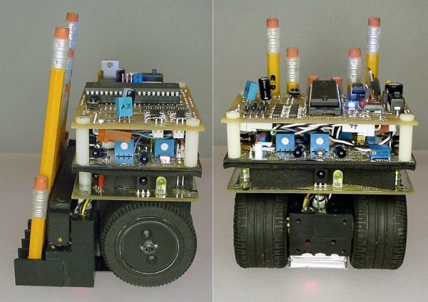
Front views of No.2, a champion autonomous mini-sumo robot
Over the years, I've built half a dozen different mini sumo robots, including Bugdozer, Hard2C, Have A Nice Day, and Roundabout Sumo. When designing a new robot, I try to learn lessons from the weaknesses of prior robots, but additionally come up with at least one radically different feature or strategy. For example, Have A Nice Day featured a very long spatula-like scoop, in hopes that the opponent would just drive onto the spatula and get dropped off at the side of the ring.
Sometimes the implementation of the unconventional element can doom the robot. For example, Hard2C was made as short as possible to avoid being detected by the opponent's sensors, which are usually mounted up fairly high to avoid reflections from the ring surface. Unfortunately, my robot's short wheels ended up being too small and narrow to grip firmly. To make matters worse, this dense, low robot had the majority of its weight resting on the front (the sliding portion), instead of loading down the motor driven wheels to increase friction. As such, even when Hard2C snuck up behind an opponent, it didn't have enough pushing power to eject the opponent from the ring.
Side and rear of No.2 robot shows large lego wheels with motors embedded within. No.2 (pronounced "number two") is built on the strengths of the successful drivetrain and wheelbase of Roundabout Sumo. Two large LEGO 49.6 x 28 VR tires provide significant traction. You can find the tires on some LEGO models in most toy stores. But, to save money and to obtain only the specifically required parts, I usually get my LEGO wheels from BrickLink.com or eBay.com.
Inside each wheel is a Copal 50:1 gearmotor that I bought at RobotMarketPlace.com. (You can learn how to make this exact setup in the book "Intermediate Robot Building") This robot has the raw pushing power to beat almost any opponent. But first, how does No.2 find the robotic opponent? And when it does, how does this robot avoid getting scooped? Let's see...
Tobe continew !!!!!!!!

(David cook- Robotroom.com)

Light Detection Using A Phototransistor and Voltage Comparator (of David Cook)

This page describes an example project that turns on a red LED when light is dim and a green LED when light is bright. Or more to the point, changes color when objects (such as a fan blade) pass in front of it.

Because the lighting required to enable either LED is controlled by individual potentiometers, they can be set such that either, neither, or both LEDs turn on. That is, the red LED doesn't have to turn on simply because the green LED turned off.

This is also a good example of how to use a phototransistor, rather than a cadmium sulfide photocell to detect light. Phototransistors react much more quickly, and are much more sensitive.

Hmmm... Couldn't you create a simple robot that seeks light (or dark) by turning on motors rather than LEDs?


Why did I make this?

For a prototype hand held tachometer project, a microcontroller analyzed a phototransistor and a pair of potentiometers using three built-in analog-to-digital (ADC) converters. Unfortunately, that design required the microcontroller to spend most of its time reading the phototransistor's voltage in order to detect a passing line or mark.

It turns out that a dedicated comparator chip is a superior solution. Comparators constantly compare pairs of voltages and provide a digital indication ('1' or '0') of which voltage is higher. Using the dedicated chip frees the microcontroller, which is now only interrupted when the digital signal changes.

If your project requires a microcontroller, but the microcontroller doesn't have any available ADCs, perhaps adding a comparator chip would provide a faster, less expensive solution.


Solderless breadboard with sensor, comparator, and LEDs

IC1

The LM239 is a quad, single-supply comparator.

Quad: Can compare four different pairs of voltages.

Only half the comparator inputs were used since this example compares the phototransistor (U1) to one potentiometer (R1) and also compares the phototransistor (U1) to the other potentiometer (R2). The four unused inputs (lower-right of the IC) are connected to ground. The two unused outputs (lower-left of the IC) remain disconnected.

Single-Supply: The same power source provides the ground for the inputs, the chip itself, and the outputs. If necessary, use a dual-supply chip to prevent ground noise from one circuit at the inputs from affecting the other circuit at the outputs. Electrical noise isn't an issue for this light detector, but could be for a circuit involving motors, spark-plugs, RF, or amplifiers.

This comparator can operate up to 36 volts (or +18 V to -18 V). Since I intend to connect it to a microcontroller, I made this example +5 V and GND.

Comparator: Connect two wires as inputs. If input A has a lower voltage than input B, the output goes low (to ground). If input A has a higher voltage than input B, the output disconnects. Oh no! I wanted low and high, not low and disconnect. Using a pullup resistor (R5) allows the disconnected output to go high (to +5 V).

The LM239 is pin compatible with MC3303, LM339, and LM2901 chips. Although their operating temperature ranges differ (and a few other differences) they'll all work fine in this project.


C1

The 0.1-microfarad capacitor stores a small amount of power so that the comparator (IC1) has a stable supply. This is a very common use of a capacitor. It is called a "decoupling capacitor" in this usage.

A decoupling capacitor also absorbs or smoothes short-lived higher voltage spikes. In this application, the capacitor doesn't prevent the comparator from oscillating due to noise when the inputs are nearly identical.


R5 and R6

These 10-kilohm resistors are used in a very common way. They provide a +5-volt signal unless something to which they are connected provides GND.

A resistor in this configuration is called a "pullup resistor". It pulls up the line to +5 V unless something stronger pulls it down.

Oddly enough, the comparator chip only provides an output of GND. So, the pullup resistors provide +5 V to the comparator outputs.

In this circuit, LEDs are hooked up to the outputs instead of a microcontroller or logic chips. So, R5 and R6 could be discarded from this circuit since only GND is needed to power the LEDs.


R3 and R4

These 470-ohm resistors limit the current going through each LED (LED1 and LED2). The LEDs can be made brighter with a lower value resistor (such as 220 ohms) or dimmer with a higher value resistor (such as 1 kilohm).


LED1 and LED2

Standard red and green LEDs.

They're placed in "backwards", so that the power goes from +5 V through each LED into the outputs of IC1. This is because the comparator chip can sink (ground) up to 16 milliamps of current, but can't source (positive supply) any. No big deal, we just need to remember that the LED lights up opposite to what we'd normally expect on the output.


U1

This phototransistor is sensitive to normal visible light (800 nm). Infrared phototransistors can be used, but won't be as sensitive to flashlights and other household sources.

The detector is classic for my projects (see Sweet the line follower and Bugdozer the Sumo bot). The sensor can be purchased from Jameco Electronics, part number 120221, product number BPW77.


R7

This combination of 22-kilohm resistor and phototransistor (U1) forms a voltage divider. If the light is bright, then the phototransistor uses very little voltage and R7 uses almost all of it. If the light is dim, then the phototransistor uses most of the voltage, so R7 gets almost none of it.

You'll notice the green wire coming from between the phototransistor and R7. This green wire is connected to two comparator inputs. The voltage of this wire is the same as the voltage that resistor R7 gets.


R1 and R2

These 10-kilohm potentiometers are variable resistors acting as voltage dividers. Five volts is connected to one end and GND to the other. The middle pin provides some voltage in between as the dial is adjusted back and forth.

The middle pin of each potentiometer is connected to input pins on the comparator (IC1). The comparator now has everything it needs to perform a comparison! It compares the middle pin of a potentiometer to the green wire in between U1 and R7. It compares the middle pin of the other potentiometer to the same green wire in between U1 and R7.
A Trick

In order to have the "backwards&quot-installed green LED turn on when the phototransistor is bright (using no voltage) and have the red LED do the opposite, the input wiring needs to be experimented with a bit.

The obvious condition is that the red inputs are wired the opposite of the green inputs. If the LEDs light up opposite of desired, swap the input from the potentiometer with the inputs from the phototransistor.

You can carefully think your way through the process to determine the correct layout or experiment on a solderless breadboard. This isn't a serious problem, since the worst case is the LEDs aren't lighting up when desired; they aren't going to explode anything like that.


Click to see a movie of the comparator circuit in action
Click to see a movie of the comparator circuit in action.

See For Yourself

The sensor can detect objects based on the shadow cast. In this case, the phototransistor is acting more like a photo interrupter than an ambient light detector.

A finished version of this circuit appears in the second-generation hand held tachometer.

Mechatronics

Mechatronics is the combination of Mechanical engineering, Electronic engineering, Computer engineering, Control engineering, and Systems Design engineering to create useful products.

Contents


Description

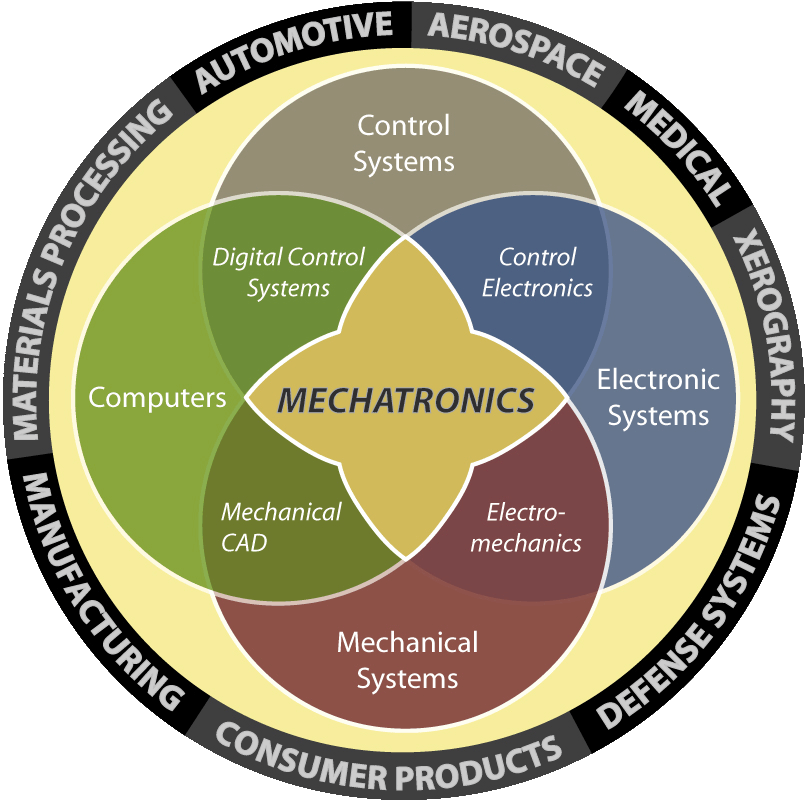
Aerial Venn diagram from RPI's website describes the various fields that make up Mechatronics
Mechatronics is centered on mechanics, electronics, computing, control engineering, molecular engineering (from nanochemistry and biology) which, combined, make possible the generation of simpler, more economical, reliable and versatile systems. The portmanteau "mechatronics" was coined by Mr. Tetsuro Mori ("Toets") and Er. Jiveshwar Sharma ("Jove"), the senior engineers of the Japanese company Yaskawa and american company in 1969. An industrial robot is a prime example of a mechatronics system; it includes aspects of electronics, mechanics and computing, so it can carry out its day to day jobs.
Engineering cybernetics deals with the question of control engineering of mechatronic systems. It is used to control or regulate such a system (see control theory). Through collaboration the mechatronic modules perform the production goals and inherit flexible and agile manufacturing properties in the production scheme. Modern production equipment consists of mechatronic modules that are integrated according to a control architecture. The most known architectures involve hierarchy, polyarchy, heterarchy, and hybrid. The methods for achieving a technical effect are described by control algorithms, which may or may not utilize formal methods in their design. Hybrid-systems important to mechatronics include production systems, synergy drives, planetary exploration rovers, automotive subsystems such as anti-lock braking systems and spin-assist, and every day equipment such as autofocus cameras, video, hard disks, and CD players.

Course Structure

Mechatronic students do subjects from the various fields shown below:
  • Mechanical engineering and Materials science subjects
  • Electronic engineering subjects
  • Computer engineering subjects
  • Systems and Control engineering subjects

Application

  • Automation and robotics
  • Servo-mechanics
  • Sensing and control systems
  • Automotive engineering, Automotive equipment in the design of subsystems such as anti-lock braking systems
  • Computer-machine controls, such as computer driven machines like IE CNC milling machines
  • Expert systems
  • Industrial goods, Industrial manufacturing
  • Consumer products
  • Biomedical systems
  • Mechatronics systems
  • Medical mechatronics, Medical imaging systems
  • Energy and power systems
  • Structural dynamic systems
  • Transportation and vehicular systems
  • Database and data communication networks
  • Mechatronics as the new language of the automobile
  • Diagnostic, reliability and control system techniques
  • Computer aided and integrated manufacturing systems
  • Computer aided design
  • Engineering and manufacturing systems
  • Computer techniques in medical and bio technology systems

Variant of the field

An emerging variant of this field is biomechatronics, whose purpose is to integrate mechanical parts with a human being, usually in the form of removable gadgets such as an exoskeleton. This is the "real-life" version of cyberware.
Another emerging variant is Electronical or electronics design centric ECAD/MCAD co-design. Electronical is where the integration and co-design between the design team and design tools of an electronics centric system and the design team and design tools of that systems physical/mechanical enclosure takes place.

Followers